IBS (Integrated Bridge System)
The total Navigation System is based on «IBS» concept (Integrated Bridge System)
The navigation system will adopt and follow the latest international standards for Navigation Systems, defined by IMO and IEC.
Standards are followed for; Navigation radars, ECDIS, Speed log, Echo sounder, DGPD/GPS,
AIS, DPS and Autopilot/Track pilot system, Multiloading Online Control Stability System.
The main Navigation sensors/systems:
- Dual Navigation ARPA Radar system (S and X-band)
- LPI Radar Sensor
- Fully duplicated ECDIS system with the charts server
- Fiber-optic gyro system
- Fully duplicated INS (Inertial Navigation System)
- Dual action speed log (water track speed and bottom track speed)
- Passive speed log (magnetic log or pressure log)
- Two independent satellite based position equipment (DGPS-GPS/GLONASS;
different manufacturers)
- Satellite independent positioning system or Laser based positioning system
- Automatic Identification System AIS
- Track-pilot system (functions as a transfer Autopilot)
- Meteorological instruments
- Xenon and Halogen search lights
- Whistle
- Navigation and signal lights
- Data recorder and play-back facility for Navigation Information
- Navigation Information Display
- Navigation Data servers for transferring the information to IMCS C2 and ANCS-System
- Time server unit
- Dynamic Positioning System (DP-System)
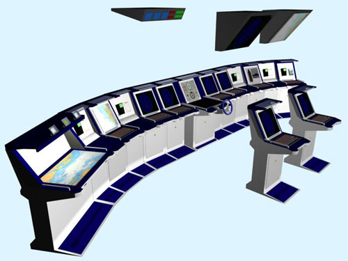
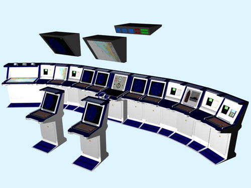
Wheel house consoles are part of the Navigation System supply.
Tentative wheel house arrangement is illustrated in Appendix 1.
Consoles will also house necessary additional components for IMCS C2 and ANCS-System, propulsion/steering system and for machinery monitoring, required to be operated on bridge.
All displays in the wheel house are high contrast TFT-type displays. Display size and modes are according to requirements.
1.2 Navigation System integration with other ships systems.
Following figure illustrates the navigation System integration to other ships systems.
Navigation System to Engine Monitoring System
- Display of Engine and propulsion Information to bridge operators
- Transfer of navigation information to Engine monitoring system
Navigation System to IMCS C2 and AWW-System
- Transfer of Navigation Information data to IMCS C2 and AWW-System
- Transfer of ARPA Tracked targets to IMCS C2 and AWW-System
- Transfer of Route Information from NAV-System to IMCS C2 -System
- Transfer of Route Information from IMCS C2 -System to NAV-System
- Transfer of high speed hull motion information to IMCS C2 and AWW-System
Navigation System to Dynamic position system
- Transfer of Navigation Information data to DP-System
- Transfer of Route information between NAV-System and DP-System
Dynamic position system to IMCS C2 -System
- Transfer of route and command information from IMCS C2 -System to DP-System
Dynamic position system and Propulsion Control system
- Transfer of Propulsion commands and feed-backs from DP-System to Propulsion control system
Navigation System and Dynamic position system to Chart Server
Enquires and its Parameters of specified Area in a specified Scale using specified Palette.
- Building of Chart of specified Area in a specified Scale using specified Palette.
Chartss Contents is limited by a list of Chart Layers.
- Getting of Chart Object under a specified small area.
- Getting of Alarms for a specified Area.
Chart Server to Navigation System and Dynamic position system
Results of Enquires
- List of Chart Objects.
- List of Alarms.
2 Navigation System components
Navigation Radar System is composed of following units:
- S-Band 30 kW down mast transceiver with 12 antenna unit
- X-Band 25 kW down mast transceiver with 9 antenna unit
- Two fully independent ARPA radar displays with built-in radar inter switching unit
- Radars are operated from UPS power source (3phase 230VAC)
- ARPA displays are 23.1 TFT screens, conforming to the standards for IMO ARPA systems
ARPA Radar system includes following special features:
- Transfer of tracked ARPA targets to ECDIS
- Transfer of user created synthetic map information from ECDIS to ARPA displays
- Presentation of route information and track information from ECDIS
- Presentation of curved EBL, initiated from ECDIS/Track steering system
- Transfer of Radar Raw image to IMCS C2 and AWW-System
- Transfer of Tracked Targets to IMCS C2 and AWW-System, via Navigation Data Server units
- Integration of ARPA displays to LPI-radar, control of LPI radar and display of LPI radar video information on ARPA display
- Radar transmission blanking output
2.2 LPI Radar Sensor and Processor
are defined at later stage.
LPI radar could be fully integrated to ARPA radar system
2.3 Fully duplicated Chart Server
-
The world-wide database of Electronic Navigational Charts
(ENC) for all available standard scales. Weekly updates.
- Source data in S57 standard, V3.1 version or more recent.
- Display of all cartographic components in accordance with
S52.
- Mercator projection with WGS-84 datum or:
-Transverse Mercator
- UTM (Gauss-Krüger)
- Polar
- Radar
- Cylindrical
- Orthographic
- Stereographic
- Gnomonic
- Base, Standard, Other Display as specified in IEC61174.
- More detailed information layers in accordance with Viewing
Groups specified in S57.
- All ECDIS Palettes: DAY-BRIGHT, DAY-WHITEBACK, DAY-BLACKBACK,
DUSK, NIGHT.
- Paper chart and Simplified chart symbols.
Area,
Scale,
Projection,
Set of layers,
Shallow, Safety and Deep Contours,
Palette.
- Alarm selection. Finding of Alarms, e.g.:
Crossing of Safety Contour, Cautionary and special Areas
Approaching to an Obstruction
Additional functions:
- Displaying and use of Additionally Military Layers AML in accordance with STANAG-7170 and STANAG-4564 standards.
- Receiving, Converting and Displaying of Sea Ice Charts produced by National Ice Center or other organization. Sea Ice Charts have been displayed as an additional chart layer
- Navigational Calculator allows to recalculate coordinates between any 2 Ellipsoids in accordance with S60 standard.
- Use of DEM (Data Elevation Model) Databases to get information about height of any point on the Earth.
Two fully independent ECDIS are included in the NAV-SYSTEM complying with following standards:
- IMO resolution A.817(19), performance standard for ECDIS
- IEC61174, Operation and performance, method of testing
- IEC60945, EMC/Environment/General requirements
Following main functions are included:
- Display of vector charts (IHO/S57 edition3) or Raster charts (ARCS)
- Presentation of Additional Military Layers (AML)
- ECDIS Computers and displays are supplied from UPS power source
- Two ECDIS computers are working in harmonised mode, allowing automatic update of data based in both ECDIS computers
- Continuous monitoring of ship position through multi-sensor Kalman filter processing using;
GPS, DGPS SDME (through the water or ground tracking speed log), gyro compasses and radar echo reference
- Route planning and monitoring
- Grounding warning and safe depth contours
- Superimposing the radar raw video on the electronic chart
- Target vectors and data from the navigation ARPA tracked targets
- Onboard generated safety maps, routes and areas which can be overlaid also on ARPA screens
- Area dependent and user defined notebook, which will inform user automatically when the ship reaches the programmed area
- Built-in voyage data logging feature, as required by ECDIS performance standard
- Integration of Automatic Identification System (AIS) in order to display other targets (carrying AIS) on ECDIS screen. Read out of detailed ship information supplied by AIS
- Perform the Automatic Track steering (in conjunction with Track Steering Device) along
a planned route. Continuous monitoring of set safety limits and warnings when exceeding safety limits or arrival in next way point
- Display of own ship future positions (predictor), based on own ship movement measured
from position equipment, gyro system and speed log
- Different chart presentation modes; North-up, Course-up, Head-up, Relative motion and True motion
- Receiving, Converting and Displaying of Sea Ice Charts produced by National Ice Center
or other organization. Sea Ice Charts have been displayed as an additional chart layer
ECDIS will accommodate a number of sensors to be connected, with appropriate international standards (IEC-61162-1)
Additional features for mine searching operation:
- Mine searching plans initiated in IMCS C2-SYSTEM, are transferred to ECIDS system
Navigation Gyro compass system includes following main units:
- LFK95 Fiber-optic gyro compass
- Interface and power supply unit (IPSU)
- Navigation Gyro compass control panel
- Analog repeaters in steering gear room
- Digital repeaters in wheel house
- Transmitting Magnetic compass
- Switch over unit and facilities to select the System Gyro Compass as the main source
for heading information to all navigation sensors (ARPA displays, ECDIS, Track pilot etc.)
Fiber-optic gyro compass supplies the following information to navigation system:
- Ships heading
- Ships rate Of Turn
- Ships Roll and Pitch information
- The ships heading information is available in analog format (Stepper output) and in serial format (IEC61162). The serial format is available both in standard 4800b/s and on higher serial transmission rates (up to 38.400b/s)
Navigation Gyro information is available in Ethernet Data format via Navigation Data Servers
2.6 Fully duplicated INS (Inertial Navigation System)
Two LSR-85 Inertial Gyro Systems are included in the Navigation System.
Following units are included:
- Two LSR-85 Inertial Master Gyro units
- Two Gyro compass control panels
- Switch Over Unit and Switch Over Unit control panel
- MIPSU interface unit (Interface to Navigation System)
Following information is available in INS:
- Ships heading
- Ships Rate Of Turn
- Ships Roll and Pitch Information
- Body velocities; X, Y and Z
- Accelerations; X, Y and Z
and on HDLC protocol.
Sensors, which require fast update rate information, are connected directly to INS.
Normal navigation systems (i.e. ARPA radars) can not scope with HDLC protocols and high speed data streams, therefore the information is transformed to a commonly used (in navigation systems) data formats.
System Gyro information is available in Ethernet Data format via Navigation Data Servers.
Following information is also available to DP-System
- Ships heading
- Ships Rate Of Turn
- Ships Roll and Pitch Information
- Body velocities; X, Y and Z
- Accelerations; X, Y and Z
2.7 Dual action speed log (water track speed and bottom track speed)
Dual Action speed log system is included in the Navigation system.
The system supplies both Water Track and Bottom Track information to Navigation system sensors.
Water track speed is used by ARPA, radars according to IMO rules.
The system has two-function log unit, working both on bottom track principle and on water track.
System includes required amount of interfaces to navigation systems, and necessary amount
of speed repeaters, distributed in wheel house and engine control room.
Water track speed log has the measuring frequency of 4Mhz and the bottom track is working
on 150KHz frequency.
Bottom track speed log can be switched off at any time, in order to stop the transmission
on 150KHz frequency.
The speed log system includes the following main units:
- Speed log electronic unit
- Speed log distribution unit
- Transducer unit with gate valve
- Four digital repeaters
- Speed log simulation unit (manual speed input facility)
- 200p/NM outputs to ARPA radars and Autopilot
Speed log information is distributed to IMCS C2 and AWW-System via Navigation Data Servers.
Ships speed information to DP-System is also provided
Navigation echo sounder function is included in the navigation system, as a part of standard equipment for navigation.
Navigation echo sounder has the following units and features:
- Graphical display, which is also used as «play-back» media for depth history.
- Transducer
- IEC61162-1 outputs to other Navigation systems
Echo sounder information is distributed to IMCS C2 and AWW-System via Navigation Data Servers.
2.9 Two independent satellite based position equipment (DGPS - GPS/GLONASS)
Two independent satellite based (DGPS - GPS/GLONASS) receivers are included in the Navigation System.
Following special features are included:
- Possibility to receive correction signals from external differential correction source (RTCM- 104 format)
Position information to IMCS C2 and AWW-System is transferred via Navigation Data Servers.
Position information output to DP-System is also provided.
2.10 Satellite independent positioning system or Laser based positioning system
Additional position reference system, independent to satellite based system, is included.
The position system is based either on Radio Navigational or on Laser principle.
The position information from satellite independent system is used in Navigation system, IMCS C2 and AWW-System and in DP-System.
2.11 Automatic Identification System AIS
Automatic Identification system (AIS) is included.
Special features:
- Own ship transmission can be suppressed on operators request
- AIS targets are transferred to ECDIS and IMCS C2 and AWW
2.12 Track-pilot system (functions as a transfer Autopilot)
- Normal Autopilot function is used when the setting of course, turns etc. are initiated manually
- The Trackpilot function is enabled when the Autopilot receives course and track information from ECDIS (pre planned route)
Main functions of the Autopilot/Trackpilot are:
- Speed Adaptive course keeping function
- Radius controlled turns
- Selection of ships loading conditions
- Selection of ships steering accuracy (Economy, Medium, Precise)
- Connection to heading reference system and Speed log
- Off course monitoring and respective alarm
- Proportional rudder order or «bang-bang» rudder order available
- Serial data connection to ECDIS (External track steering function)
- Track steering operation, when assisted by ECDIS
2.13 Meteorological instruments
Following meteorological instruments are included and integrated in Navigation System:
- Wind speed and direction
- Outside air temperature
- Outside air pressure
- Outside air humidity
The meteorological Information is displayed in wheel house by means of a Conning display and the information is also transferred to DP-System and IMCS C2 And AWW-System
2.14 Xenon and Halogen search lights
One 2000W Halogen type search light with remote controlled operation is included.
One 2000W Xenon type search light with remote controlled operation is included.
2.15 Whistle
Whistle system according to rules is provided
2.16 Navigation and signal lights
Navigation and signal lights according to rules are provided
2.17 Data recorder and play-back facility for Navigation Information
It shall be possible to record data from all sensors attached to navigation system.
Following information is recorded, at least in one Hertz frequency:
- Ships heading
- Ships speed
- Time and data
- Ships position
- Propulsion orders
- Depth
2.18 Navigation Information Display (i.e. Conning Display)
«Conning» Display, for the presentation of information from Navigation sensors and Propulsion devices, is included.
Conning display presentation includes the following information (as minimum):
- Ships heading (from selected System Gyro source)
- Ships heading from Navigation Gyro
- Rate of Turn
- Roll and Pitch
- Ships speed
- Depth and set depth alarm limit
- Meteorological information
- Route Information from ECDIS
- Propulsion information (RPM)
- Rudder angle orders and feed-back
- Bow thruster orders and feed-back
- Track-pilot status
- Steering mode
Display pages are customised and different pages are available upon operators request.
2.19 Navigation Data Servers for transfer of Navigation data information
to IMCS C2- system and AWW
The main purpose of Navigation Data Server is to supply all navigation related information to IMCS C2-System and AWW.
The protocol between the Navigation Data Server and IMCS C2 and AWW- System is based on Finnish Navy SQ2000 data format.
Navigation data is transferred to IMCS C2 and AWW-System on Ethernet. Ethernet uses broadcast principle and the data is transmitted 10 times / second.
- Ships heading (from selected System Gyro source)
- Ships heading from Navigation Gyro
- Rate of Turn
- Roll and Pitch
- Ships body velocities
- Ships speed
- Direct position information from Position Devices
- Depth and set depth alarm limit
- Meteorological information
- ARPA Display tracked targets
2.20 Time server unit
Central Time server unit, distributing the time for Navigation-, IMCS C2- and AWW-systems, is included.
The system includes NTP-Server functions as well as ASCII-based time stamp output to Navigation Data servers and ARPA displays.
2.21 Dynamic Positioning System (DP-System)
The Dynamic Positioning system (DP-System) is used to control the ship propulsion components automatically in different needs and in different operation modes.
DP-System integrates following sensors and equipment:
- Positioning systems
- Heading sensors
- Speed log
- Main propulsion devices
- Bow thrusters
- Wind-sensor
- Others, if needed
DP-System integrates following operational functions:
- Sailing plan or direction orders, which should be followed by DP-System
- Move on planned track (slow speed or high speed tracking)
- Stay at given position (Dynamic Positioning)
- Keep heading
- Rotate around a point (fore-ship, center-ship, aft-ship or a point outside of ship)
- Translate ship position (fore, aft, side or any resultant combination)
DP-System receives track information either from IMCS C2-System or from Navigation System
DP-System tracks (either from navigation system or IMCS C2-System) are displayed in ECDIS workstations.
DP-Controls are located both in CIC and on bridge.
3 Wheel house consoles
All wheel house consoles and overhead panels are included in the Navigation System delivery.
Console configuration is tentatively described in Appendix 1.